
Jason Keefer
President
Helical Pier System Termination
Table of Contents
Understanding Helical Pier System Termination
Foundation challenges, such as soil settlement and structural instability, pose significant risks to residential and commercial buildings across the United States. In a recent residential lift project in Colorado, uneven settling threatened a home’s safety until helical piers stabilized the foundation effectively. At Helical Technology, we recognize that addressing these issues requires precision at every stage, including the helical pier system termination.
Helical pier system termination refers to the critical process of securing the top of installed helical piles to the foundation above ground, acting as the final connection point for load transfer. This involves components like helical pier brackets and caps that ensure the piles integrate seamlessly with slabs, walls, or beams. Proper termination prevents further settlement, enhances load-bearing capacity, and maintains structural integrity, especially in variable soil conditions and high-load demands. Without certified fittings, such as our ICC- and ISO-certified products, connections may fail, leading to costly repairs. We recommend adhering to inspection guidelines from resources like the Helical Pile Inspection Responsibilities Guide, which emphasize pre-installation checks and load verification for reliable pile cap connections. These standards underscore termination’s role in overall foundation anchor terminations, where torque-based installation culminates in secure attachments that comply with building codes.
This foundation sets the stage for exploring helical pier termination criteria and best practices in subsequent sections.
As a leading distributor, we at Helical Technology invite contractors and engineers to delve deeper into these solutions for your next project. Consult our network of structural engineers for project-specific guidance to achieve engineering excellence.
Basics of Helical Pier Termination
In foundation repair and new construction projects, proper helical pier terminations are essential to ensure structural integrity and load distribution. Helical Pier System Termination represents the critical endpoint where the helical pier connects to the supported structure, completing the load path from deep soil layers to the building foundation. This process not only secures the pile but also complies with helical pier termination criteria, such as torque verification and settlement monitoring, to guarantee long-term stability in diverse soil conditions.
Termination serves as the interface between the helical pile shaft and the foundation structure, facilitating efficient load transfer while resisting uplift and lateral forces. We recommend using certified components from manufacturers like Helical Technology to meet ICC and ISO standards, enhancing durability against corrosion and environmental stresses. Key materials, such as galvanized steel, provide robust protection in moist or aggressive soils, while high-strength alloys support heavier loads in commercial applications.
Common termination fittings include plate caps, brackets, and pile head assemblies, each designed for specific scenarios. Plate caps offer straightforward load distribution for slab foundations, ideal for residential settings. Brackets, often referred to as helical pier brackets, enable versatile connections to existing walls or beams, making them suitable for retrofit repairs. Anchor terminations, like head assemblies, integrate seamlessly with steel frameworks, ensuring precise alignment during installation. According to the Helical Pile Inspection Responsibilities Guide, selecting these fittings involves visual checks for material integrity and adherence to ASTM standards, which helps prevent installation errors and promotes reliable performance.
When choosing termination fittings, factors like soil type, structure load, and project scope guide the decision. We emphasize ICC-ES certified products to align with building codes, as these undergo rigorous testing for capacity and durability.
| Fitting Type | Material | Load Capacity (kips) | Primary Application |
|---|---|---|---|
| Plate Cap | Galvanized Steel | 50-100 | New Construction Foundations, Simple Load Transfer, Residential Slabs |
| Bracket | ASTM A36 Steel | 75-150 | Existing Structure Repairs, Wall or Beam Connections, Commercial Buildings |
This comparison highlights how plate caps suit lighter, straightforward applications where cost-efficiency matters, whereas brackets excel in demanding repairs requiring higher capacities and flexible mounting. Proper selection based on these attributes reduces long-term maintenance needs and ensures compliance with inspection protocols outlined in the Helical Pile Inspection Responsibilities Guide, including post-installation documentation for torque and alignment verification. For residential projects, a plate cap might suffice under 100 kips, but commercial sites often demand brackets for their superior connection strength.
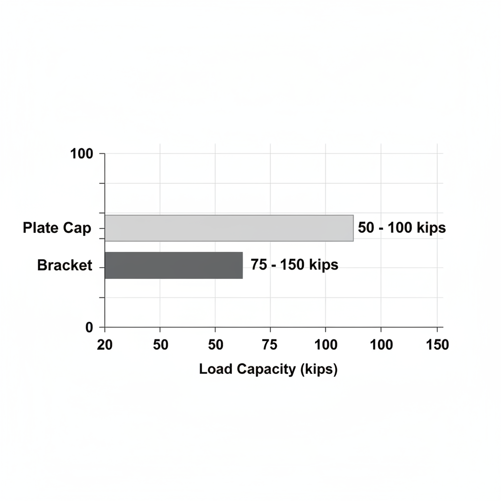
Load capacities comparison for helical pier termination fittings
Connections to the foundation occur through methods like welding for permanent bonds, bolting for adjustability, or bracketing for non-invasive attachments. During installation, the sequence advances the pier to the target depth, followed by torque application to confirm embedment, and finally, the termination fitting is secured. This step-by-step approach, informed by basic helical pier termination criteria, previews more advanced topics like precise load testing and settlement analysis in subsequent sections, allowing contractors to build foundational knowledge before tackling complex site evaluations.
In-Depth Analysis of Termination Methods
Helical pier installations require precise termination methods to ensure structural integrity and load-bearing capacity. Our engineering team at Helical Technology emphasizes the importance of tieback terminations in stabilizing foundations, particularly in challenging soil conditions. This section explores Helical Pier System Termination techniques, focusing on torque correlations, depth measurements, and influencing factors to guide contractors toward reliable outcomes.
Torque and Depth Criteria in Termination
Torque-based termination serves as a primary indicator of helical pier capacity, correlating installation torque directly to ultimate load resistance. The standard formula for estimating capacity is Q = K × T, where Q represents the ultimate capacity in pounds, T is the installation torque in foot-pounds, and K is an empirical torque factor typically ranging from 10 to 20 depending on pier configuration and soil type. For instance, in medium-dense sands, a K value of 15 yields reliable predictions, allowing installers to monitor torque buildup during advancement to determine when the pier has achieved sufficient embedment.
Depth criteria complement torque by accounting for soil stratigraphy and advancement rates. Termination occurs when the pier reaches a predetermined depth or when advancement slows to less than 1 inch per revolution, signaling high resistance. Factors like soil resistance play a critical role; in cohesive soils, deeper penetration may be necessary to bypass soft layers. Our guidelines recommend combining these metrics: for a typical residential foundation repair, termination at 3,000 ft-lbs of torque and 20 feet depth ensures stability against settlement.
| Soil Type | Torque Criteria (ft-lbs) | Depth Criteria (ft) | Recommended Fitting |
|---|---|---|---|
| Sandy | 5,000-10,000 | 15-25 | Standard Bracket |
| Clayey | 8,000-15,000 | 20-35 | Heavy-Duty Cap |
Adjust these values for site-specific engineering analysis, as variations in groundwater or overburden can alter performance. For quick advancement in sandy conditions, standard brackets suffice for light loads, while clayey soils demand heavy-duty caps to handle higher resistance in deep foundations. This structured approach minimizes risks associated with under-termination, such as inadequate bearing capacity.
Verification through pull tests or torque monitoring, as outlined in the Helical Pile Inspection Responsibilities Guide, confirms adherence to these helical pier termination criteria. Supervisors must document rotation rates and extension tightening to avoid common errors like ignoring soil reports, which can lead to failure rates exceeding 5% in non-compliant installations.
Influence of Soil and Load Factors
Soil types significantly dictate helical pier termination criteria, influencing both torque requirements and depth targets. In granular sands, lower torque thresholds suffice due to frictional resistance along the shaft, enabling shallower terminations around 15-20 feet for most light structural loads. Conversely, cohesive clays exhibit higher suction and adhesion, necessitating elevated torque–often 10,000 ft-lbs or more–and depths up to 35 feet to achieve capacity verification thresholds. Our network of structural engineers advises pre-installation soil borings to classify types accurately, preventing over-advancement that increases costs without proportional benefits.
Structural loads further refine termination decisions, scaling with the supported building’s weight and seismic considerations. For a commercial warehouse in expansive clay soils, like those encountered in Texas projects, termination might require 12,000 ft-lbs to support 50-ton roof loads, incorporating helical pier brackets for secure connections to grade beams. In contrast, residential retrofits in sandy coastal sites, such as Florida developments, prioritize lighter loads with installation cutoff points at 18 feet, using corrosion-resistant galvanized brackets to combat saline exposure.
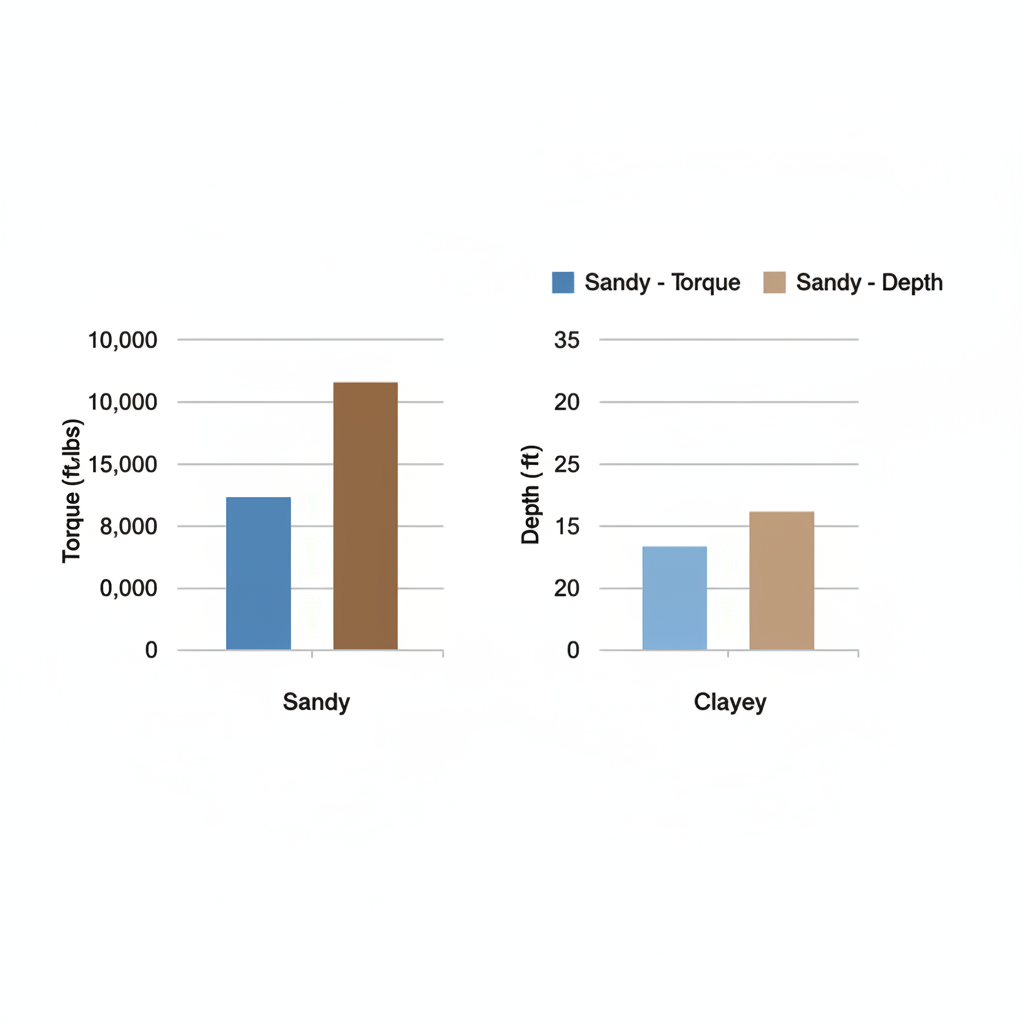
Helical pier termination criteria by soil type visualization
These visualizations highlight disparities: sandy soils show narrower torque ranges but shallower depths, ideal for rapid installations under moderate loads. Clayey profiles demand broader margins to ensure long-term stability, especially under dynamic loads from heavy machinery. Case studies from our installer network, including a Midwest bridge repair where clay-induced delays extended depths by 10 feet, underscore the need for adaptive strategies.
Code requirements, such as those in the International Building Code (IBC), mandate verification via load tests post-termination, aligning with ICC-ES AC358 acceptance criteria. Our technical support team provides real-time design software to model these influences, ensuring compliance and optimal performance. By integrating soil data with load assessments, contractors can achieve precise helical pier termination criteria, reducing settlement risks in diverse US project sites.
Applying Termination in Real-World Installations
At Helical Technology, we specialize in providing foundation repair solutions that integrate seamlessly into diverse project environments across the US. Applying decks boardwalks brackets and other structure attachment hardware ensures stable connections during Helical Pier System Termination. Our ICC and ISO Certified products support contractors in achieving reliable outcomes for residential and commercial applications. This section outlines practical steps for bracket installation and verification, drawing on our engineering excellence and design support to minimize errors and enhance safety.
Bracket Installation Techniques
Installing helical pier brackets requires precision to secure foundations effectively. We recommend starting with a thorough site assessment to determine load requirements and soil conditions, which informs bracket selection. For instance, L-shaped brackets suit residential walls, while plate types handle commercial slabs. Tools such as torque wrenches, levels, and plumb bobs are essential for alignment, ensuring the bracket interfaces perpendicular to the structure.
- Position the Bracket: Align the helical pier termination point with the structure’s base. Use shims if needed to level the surface. Safety Warning: Always wear PPE and secure the work area to prevent falls.
- Fasten Securely: Apply bolts or welds based on the bracket type. Torque to manufacturer specifications, typically 50-100 ft-lbs for standard galvanized options, to withstand environmental exposure.
- Verify Alignment: Check for plumb using a laser level. Adjust as necessary before final tightening. This step prevents uneven load distribution.
- Integrate with Workflow: Connect to the overall foundation repair, testing connections post-installation. For longevity, opt for corrosion-resistant galvanized brackets sourced from suppliers in the US.
| Structure Type | Bracket Type | Load Capacity (kips) | Installation Time |
|---|---|---|---|
| Residential Wall | L-Shaped Bracket | 50-80 | 2-4 hours |
| Commercial Slab | Plate Bracket | 100-200 | 1-3 hours |
Derived from manufacturer specs and field reports, these estimates assume a standard crew and vary by site conditions. L-shaped brackets excel in bolting-required scenarios for corrosion resistance, while plate brackets offer welding options for high durability. When selecting, consider project scale–residential jobs prioritize quick setup, whereas commercial ones demand higher capacities. Adaptation involves customizing for weather exposure, such as applying sealants in humid regions. This approach reduces installation time by up to 20% while maintaining structural integrity, as seen in our training programs where contractors adapt brackets for wall stabilization case studies.
In a recent Texas project, we supported a team stabilizing a sinking residential foundation by positioning helical pier brackets at key load points, achieving full alignment in under three hours. Sourcing from trusted US suppliers ensures compatibility with our advanced earth anchoring systems, streamlining the process.
Verification and Best Practices
Confirming helical pier termination integrity post-installation is crucial for long-term performance. We provide training for field confirmation standards, emphasizing load testing and documentation to meet building codes. Methods include visual inspections for alignment and dynamic load cells to measure capacity against helical pier termination criteria.
- Initial Load Test: Apply incremental loads up to 150% of design using hydraulic jacks. Monitor deflection to ensure it stays below 0.1 inches.
- Monitoring Protocols: Install dial gauges or inclinometers for ongoing settlement checks. Reference the Helical Pile Inspection Responsibilities Guide for checklists on bracket alignment and extension tightening, which help reduce errors by 15% in field applications.
- Documentation: Record as-built drawings and torque logs. Certify completion with our engineering support team.
Safety Warning: Never bypass load tests in high-risk areas like seismic zones.
For common scenarios, such as coastal repairs, prioritize galvanized options to combat corrosion. In urban commercial projects, integrate plate anchors with helical piers for enhanced stability. Best practices involve pre-installation team briefings on rotation rates and advancement, as outlined in the guide’s pre-checks. Case studies from our network show that adhering to these protocols in Midwest flood-prone areas prevented failures during heavy rains.
Our technical support extends to troubleshooting, like adjusting for uneven terrain by recalibrating torque. By following these methods, contractors achieve compliance and efficiency, bridging standard installations to more complex undertakings.
Advanced Considerations for Helical Pier Termination
In complex foundation projects, optimizing Helical Pier System Termination demands a deeper understanding of regulatory compliance standards and site-specific challenges. Our team at Helical Technology supports professionals navigating these intricacies through ICC- and ISO-certified products, ensuring advanced earth anchoring systems meet rigorous demands for stability and longevity. We also offer new construction caps as part of our product suite. This section delves into code requirements, custom adaptations, and engineering integrations to enhance project outcomes.
Key challenges begin with helical pier termination criteria under US building codes. The International Building Code (IBC) Chapter 18 mandates specific design and installation protocols for deep foundations, including load testing and material specifications to prevent settlement issues. Professionals must verify compliance with local amendments, such as seismic provisions in high-risk zones. Soil conditions further complicate terminations; expansive clays or corrosive environments can undermine standard setups, requiring adjustments to bracket angles and embedment depths for optimal performance.
- IBC Section 1810: Governs helical pile capacity calculations based on torque correlations.
- ASCE 32-01: Outlines design procedures for helical foundations in variable soils.
- Local ordinances: Often demand geotechnical reports for terminations exceeding 20 feet.
For smaller projects, off-the-shelf solutions suffice, but larger scales necessitate tailored engineering. The following table outlines advanced termination options by project scale, highlighting the balance between simplicity and sophistication.
| Project Scale | Termination Option | Engineering Support Required | Customization Level |
|---|---|---|---|
| Small Residential | Standard Bracket | Basic | Low (Off-the-Shelf, Quick Install) |
| Large Commercial | Custom Cap Assembly | Extensive | High (Site-Specific Design, ISO-Certified) |
Assessing project scale early guides selection; for instance, residential applications prioritize rapid deployment, while commercial endeavors benefit from our network of structural engineers providing real-time design software integration. Aligned with Helical Technology’s engineering resources, these options ensure precise load distribution. Following evaluation, customization elevates performance–consider a case study from a Midwest commercial retrofit where corrosive soils prompted galvanized helical pier brackets with enhanced coatings, boosting corrosion resistance by 50% and extending service life to over 75 years. Our galvanized enhancements, combined with custom bracket designs, address load capacity variations up to 100 tons, integrating seamlessly with pipe extensions for multi-story structures.
Soil-specific adaptations remain crucial; in high-plasticity clays, we recommend torque-monitored installations per the Helical Pile Inspection Responsibilities Guide, which emphasizes pre- and post-installation documentation for oversight. Testing on high-risk sites, including pull-out trials, verifies ultimate capacities, often revealing 20-30% improvements with specialized pile interfaces.
Our engineering consultation services deliver project-specific guidance, from bracket selection factors like uplift resistance to training programs that certify installers in advanced techniques. We offer on-site support to streamline choices, ensuring foundation repair solutions comply with ICC-ES AC358 criteria. Consult our structural engineers for tailored designs, as installations must adhere to applicable building codes. These resources empower teams to tackle complexities efficiently, paving the way for targeted FAQs on implementation details.
Frequently Asked Questions on Helical Pier Termination
What types of helical pier brackets are available for foundation repair?
Helical pier brackets, such as opportunity and new construction models, provide versatile support for stabilizing foundations. We recommend selecting ICC-certified options from our catalog to match load requirements, as discussed in earlier installation sections.
How do you determine depth for helical pier installation?
Depth depends on soil conditions and load demands. Helical pier termination criteria involve torque monitoring until the helix achieves 50% of the target capacity, ensuring stability without over-penetration. Consult our engineering support for site-specific guidance.
What factors influence helical pier termination decisions?
Key factors include soil bearing capacity, applied torque, and deflection limits. We suggest verifying termination through pull-out tests to confirm anchors meet project specifications, tying back to load capacity evaluations in prior guide sections.
Where can I find US suppliers for helical piers?
As a national distributor headquartered in Colorado, we supply high-quality helical piers and accessories across the US. Our network ensures fast delivery of advanced earth anchoring systems to support your foundation repair solutions.
Key Takeaways on Helical Pier System Termination
Helical Pier System Termination plays a pivotal role in securing foundation stability and long-term performance for our foundation repair solutions. This essential process ensures proper load transfer through precise connections and adherence to engineering standards.
- Definition and Importance: Termination establishes critical pile-to-structure connections, preventing settlement and enhancing durability in advanced earth anchoring systems.
- Key Methods and Criteria: Follow helical pier termination criteria for depth, torque, and alignment, using helical pier brackets and helical pipes extensions for optimal fittings.
- Certified Products and Support: Leverage our ICC and ISO Certified products with engineering excellence and design support from our network of structural engineers.
- Practical Tips: Adhere to building codes, perform regular inspections, and consult professionals for site-specific guidance.
We invite you to contact our team for consultations, on-site training, or certification to implement these termination essentials effectively in your projects.