
Table of Contents
- Understanding Soil Bearing Capacity for Helical Piers
- Fundamentals of Soil Bearing Capacity for Helical Piers
- Installation Torque and Its Relationship to Soil Bearing Capacity
- Practical Determination of Soil Bearing Capacity for Helical Pier Design
- Advanced Considerations in Soil Bearing Capacity for Helical Piers
- Frequently Asked Questions About Soil Bearing Capacity and Helical Piers
- Soil Bearing Capacity: The Foundation of Successful Helical Pier Projects
Understanding Soil Bearing Capacity for Helical Piers
Every foundation repair project begins with a clear understanding of the subsurface conditions. Soil bearing capacity for helical piers is the maximum load the ground can support without failure. We use this critical metric to determine the depth and number of helices required to transfer structural loads into a competent bearing stratum. Geotechnical investigations — soil borings and Standard Penetration Tests — provide the site‑specific data that shape every design.
As Helical Technology notes, the required depth varies considerably by soil type, ranging from 5–15 feet in soft clay to 12–30 feet in gravel or sandy gravel. Once the bearing capacity is quantified, the depth required for a successful helical pier installation can be determined precisely. Helical piers resist loads through both skin friction along the shaft and end bearing on the helices; we verify capacity via torque monitoring correlated with ICC‑ES AC358 acceptance criteria.
Our Engineering Excellence and Design Support includes proprietary software that models local soil properties to optimize pier sizing. Still, no design is final until a licensed structural engineer reviews the soil data and the proposed configuration, confirming compliance with building codes and ensuring reliable foundation repair solutions. For project‑specific guidance, consult a structural engineer or our engineering team.
With soil bearing capacity properly evaluated, the installation team can proceed with confidence. The next section outlines how certified installers translate these engineering parameters into a secure, code‑compliant helical pier foundation.
Fundamentals of Soil Bearing Capacity for Helical Piers
Building on the introduction to helical piers as a foundation reinforcement solution, the success of every installation depends on the native soil properties. Soil bearing capacity, the maximum pressure soil can safely support without excessive settlement, is the critical parameter that controls how loads are transferred to the ground. Understanding the soil bearing capacity for helical piers begins with evaluating the ground’s ability to carry structural loads. Determining the soil bearing capacity is the first step in designing a building foundation reinforcement solution.
Engineers assess the allowable bearing capacity of the soil to size helical pier components, including helix diameter, number of helices, and minimum embedment depth, to ensure each pier reaches a competent bearing stratum. For cohesive soils like soft clay and stiff clay, the undrained cohesion strength dictates capacity; for granular soils such as loose sand, dense sand, and gravel, the internal friction angle is the controlling variable. Rock provides the highest bearing values, often exceeding 10,000 psf. These soil properties directly inform the design of our advanced earth anchoring systems. Industry benchmarks from the National Foundation Repair Association summarize these typical values.
The following table presents typical allowable bearing capacities for common foundation soils.
| Soil Type | Cohesive Strength (psf) | Friction Angle (deg) | Allowable Bearing Capacity (psf) |
|---|---|---|---|
| Soft Clay | 500 | 0 | 1000 |
| Stiff Clay | 2000 | 0 | 4000 |
| Loose Sand | 0 | 28 | 2000 |
| Dense Sand | 0 | 38 | 6000 |
| Gravel | 0 | 40 | 8000 |
| Rock | N/A | N/A | 10000+ |
Soft clay, with its low cohesive strength and zero friction angle, may support only about 1,000 psf, which is adequate for very light loads. Dense sand, with a friction angle of 38 degrees, can carry 6,000 psf, while gravel or rock can reach 8,000 psf or more. These values are benchmarks; actual bearing capacity varies with moisture content, density, and stratification. A site-specific geotechnical investigation is necessary to confirm the soil profile. Our engineering team engages with contractors to interpret soil reports and recommend appropriate helical pier configurations. Always consult a structural engineer or the manufacturer’s engineering team for project-specific design and installation guidance.
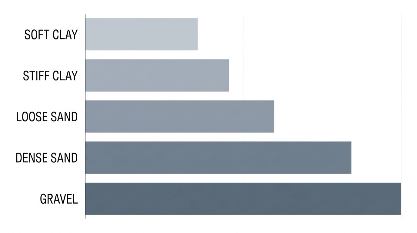
Soil bearing capacity comparison for helical pier foundation design.
With accurate soil bearing data, we can calculate the required number of helices and embedment depth for a given structural load. The helix diameter and plate count are selected to achieve a factor of safety appropriate for the structure, and our ISO-certified manufacturing ensures consistent quality. Our ICC- and ISO-certified helical pier products are engineered to match these site-specific bearing conditions, delivering a reliable foundation solution. Ultimately, determining the soil bearing capacity for helical piers guides the entire pier configuration. This understanding sets the stage for practical design applications, where load transfer and pier configuration are determined to meet structural performance criteria.
Installation Torque and Its Relationship to Soil Bearing Capacity
Understanding soil bearing capacity for helical piers is the first step; installation torque provides the most reliable field measurement of that capacity. After exploring soil properties, we turn to how torque readings serve as a real-time indicator of the soil’s resistance as the pile is installed.
Guidelines from the Deep Foundation Drilling Association and ICC-ES AC358 define the torque-capacity relationship that engineers use to estimate ultimate pile capacity.
How Installation Torque Correlates with Soil Capacity
The bearing capacity of soil for helical piles is directly inferred from installation torque because the rotational resistance encountered by the helix plates reflects the soil’s shear strength. As each helix advances into competent strata, the torque required to turn the pile increases proportionally to the load the pile can ultimately support. This linear relationship is grounded in decades of empirical data and has become a cornerstone of quality control during installation.
Contractors rely on real-time torque monitoring using hydraulic drive heads to ensure that the helical pile reaches load-bearing soil well below the frost line. We use this data not only to confirm that adequate capacity has been achieved but also to decide when additional extensions are needed—if the target torque is not reached, the pile is driven deeper until the measurement aligns with the design requirements. This procedure, detailed in Helical Technology’s technical resources, eliminates uncertainty and helps prevent future settlement issues.
While torque is a powerful field indicator, it must be interpreted through a standardized methodology. When the project engineer requires, site-specific load testing validates the torque-capacity correlation for the local soil profile, ensuring the estimated capacity matches actual performance. Understanding how torque data translates to design capacity leads us to the torque factor method.
The following table, sourced from the ADSC Helical Pile Committee and ICC-ES AC358, lists typical torque factor (Kt) ranges for various soil types:
| Soil Type | Typical Kt Range (ft^-1) | Source |
|---|---|---|
| Soft Clay | 3 – 5 | ADSC/ICC-ES |
| Stiff Clay | 5 – 8 | ADSC/ICC-ES |
| Loose Sand | 6 – 10 | ADSC/ICC-ES |
| Dense Sand | 8 – 12 | ADSC/ICC-ES |
| Gravel | 10 – 15 | ADSC/ICC-ES |
Source: ADSC Helical Pile Committee and ICC-ES AC358.
These ranges reflect empirical data and are the industry standard for initial capacity estimation. However, the values should be adjusted based on site-specific conditions and validated through load testing when required.
The Torque Factor Method and Capacity Equations
To convert installation torque into an estimated ultimate capacity, the industry uses the torque factor (or Kt), defined by the simple equation:
Qult = Kt × T
where Qult is the ultimate pile capacity (in pounds or kips), T is the measured installation torque (in ft-lb), and Kt is the empirical torque factor (in ft⁻¹). The value of Kt depends on soil type, helix geometry (diameter, pitch, number of helices), and installation conditions such as the rate of advance and shaft friction.
The table above provides typical Kt ranges for common soil types. In general, stronger soils yield higher K factors: dense sand and gravel demand more torque per unit of ultimate capacity than soft clay. These values serve as starting points; final Kt selection should incorporate site geotechnical data and project requirements. Using the correct Kt ensures that the helical pier capacity from torque is neither overestimated nor underestimated, safeguarding the structure’s long-term performance.
Helical Technology’s helical piles are ICC-ES certified, so their design adheres to AC358 acceptance criteria and must be installed per applicable building codes. Our engineers and design software assist contractors in selecting the appropriate Kt for a specific project in Littleton or anywhere in the country, ensuring compliance and reliability.
As a best practice, we recommend that a structural engineer or our engineering team verify the torque-capacity relationship for critical applications. Always consult a structural engineer or the manufacturer’s engineering team for project-specific design and installation guidance. With the torque factor method established, we can now move to applying it for practical capacity estimation in the next section.
Practical Determination of Soil Bearing Capacity for Helical Pier Design
Determining the soil bearing capacity for helical piers is the foundational step in designing any advanced earth anchoring system. For helical pier design, the bearing capacity of soil directly dictates the helix plate size and configuration required to support structural loads. A reliable determination begins with a thorough geotechnical investigation that informs both field verification and final configuration.
Conducting a Geotechnical Investigation
A well-planned geotechnical investigation provides the soil bearing capacity determination needed to model pier performance. Before mobilizing a drill rig, we recommend reviewing project structural plans to define design loads and the anticipated depth of the helical pier embedment. The following steps outline a typical site-specific investigation:
- Review project plans and define the required design loads for each pier location.
- Perform soil borings at representative pier locations, advancing the borehole to at least 1.5 times the expected pier depth.
- Conduct Standard Penetration Tests (SPT) at regular intervals during boring to assess soil density and relative strength.
- Collect disturbed and undisturbed soil samples for laboratory classification, including Atterberg limits, grain size distribution, and moisture content.
- Identify the depth of competent bearing strata and evaluate groundwater conditions.
- Compile the data into a geotechnical report that maps soil profile variations and informs pier design parameters.
Results from borings and lab work directly influence the torque factor used in the field verification step.
Field Testing and Torque Correlation
During installation, the torque required to advance a helical pier is continuously recorded and used to estimate soil bearing capacity for helical piers at each placement depth. The industry-standard torque factor method relates final installation torque to ultimate capacity through an empirical coefficient Kt. According to the National Foundation Repair Association, recommended Kt values vary by soil type and are derived from extensive load testing programs. The ADSC Helical Pile Committee provides complementary guidelines that help standardize Kt selection across different geotechnical conditions.
Several on-site verification methods exist, each with distinct advantages and limitations:
| Method | Description | Advantages | Limitations |
|---|---|---|---|
| Torque Correlation | Estimates capacity from installation torque using Kt factor. | Real-time, no extra equipment, widely accepted. | Requires calibrated Kt; less accurate in layered soils. |
| Static Load Test | Applies a known load and measures settlement. | Direct measurement, highest accuracy. | Time-consuming, expensive, requires reaction system. |
| PDA Test (Dynamic) | Uses dynamic analysis of pile driving. | Faster than static test, can test multiple piles. | Requires specialized equipment and expertise. |
| Proof Test | Applies a proof load to confirm capacity exceeds a threshold. | Less expensive than full static test. | Does not provide ultimate capacity, only pass/fail. |
While torque correlation gives immediate feedback during installation, its accuracy depends on a calibrated Kt factor. Project-specific soil conditions—such as expansive clays that our regional data shows can fluctuate in volume by as much as 4.5 percent—require careful interpretation of the torque‑capacity relationship. Our engineering team helps contractors calibrate Kt factors for their local geology using the torque data collected on site.
Applying Capacity Calculations in Design
Once the bearing capacity of soil for helical pier design is established from field torque readings and, when necessary, load tests, it is used to select the correct helix plate diameter, thickness, and number of helices. The design must satisfy both individual bearing and overall pile structural capacity per ICC-ES acceptance criteria. Our real‑time design software integrates the soil bearing values with project loads to specify an optimized helical pier configuration, and all our helical piers are ICC and ISO Certified products offering a service life of at least 75 years when installed to manufacturer specifications.
Proper application of soil bearing capacity data ensures that each pier is sized to transfer loads into competent bearing strata while avoiding over‑mobilization of weaker near‑surface soils. Engineering Excellence and Design Support remain central to our process: a network of structural engineers works directly with contractors to validate assumptions and adjust configurations for unusual soil profiles. This coordination directly informs the helical pier configuration that will be detailed in the subsequent section, where we show how to translate calculated capacity into complete pier specifications.
Consult a structural engineer or the manufacturer’s engineering team for project‑specific design and installation guidance. With our Littleton‑based technical support and ICC/ISO‑certified product line, Helical Technology equips foundation repair professionals to turn accurate soil bearing data into reliable deep‑foundation solutions.
Advanced Considerations in Soil Bearing Capacity for Helical Piers
Beyond basic bearing capacity concepts, several advanced factors influence the soil bearing capacity for helical piers. These elements demand careful engineering analysis to ensure our ICC- and ISO-certified helical piers deliver reliable support in variable subsurface conditions.
Soil type plays a defining role in the bearing capacity of helical piers. Cohesive clays exhibit strong torque correlation—the relationship between installation torque and ultimate capacity—allowing predictable load transfer. Granular sands and silts, however, often show weaker correlations and require site‑specific calibration. At Helical Technology, our advanced design software (available at helicaltechnology.com) models soil‑structure interaction for each project. This tool integrates soil parameters and torque data to refine bearing capacity predictions, streamlining pier selection.
Groundwater fluctuations further complicate capacity assessment. A rising water table reduces effective stress and soil strength, diminishing the helical pier load capacity, while seasonal drying can cause swelling or shrinkage in clay layers. Because of these variations, site‑specific soil testing such as Standard Penetration Tests (SPT) or Cone Penetration Tests (CPT) is indispensable. These subsurface conditions collectively determine the soil bearing capacity for helical piers. The International Building Code (IBC), published by the International Code Council and accessible through the Digital Codes Premium Printing Tools, mandates such soil investigations, and adherence to ICC-ES AC358 acceptance criteria verifies that helical pier designs meet rigorous performance standards.
Our product certifications align with these code requirements. The IBC and ICC-ES AC358 criteria directly inform our engineering support, and our network of structural engineers can review soil reports to provide project‑specific guidance. We recommend consulting a structural engineer or contacting our team for detailed design assistance; all installations must comply with IBC and AC358. When these advanced considerations are properly managed, helical piers provide dependable foundations even in challenging ground, and our engineering team stands ready to assist with design verification. The next section will apply these principles to practical design calculations and real‑world case studies.
Frequently Asked Questions About Soil Bearing Capacity and Helical Piers
Soil bearing capacity for helical piers is key to foundation design. Below we answer top FAQs.
What Is Soil Bearing Capacity for Helical Piers?
Soil bearing capacity is the load soil can safely support; helical piers transfer loads to deeper, competent strata where capacity is adequate.
How Does Expansive Clay Soil in Texas Affect Foundation Pier Performance?
Expansive Texas clays can shift foundations. Helical piers bypass this active zone; consult a structural engineer for project‑specific analysis.
How Do Helical Piers Compare to Concrete Piers in Terms of Soil Bearing Capacity?
Unlike concrete piers, helical piers reach deeper load‑bearing soil capacity, providing greater stability in expansive soils.
How Long Do Concrete Piers Last in Texas Soil?
Our concrete pier foundation repair in Texas FAQ notes concrete piers last about 50 years, but soil fluctuations can compromise performance. ICC‑ISO certified helical pier systems routinely exceed 75 years.
For Engineering Excellence and Design Support in foundation repair, contact our team.
Soil Bearing Capacity: The Foundation of Successful Helical Pier Projects
Soil bearing capacity is the maximum load per unit area the ground can support without failure and is fundamental to helical pier success. Factors like soil type, such as clay, sand, or silt, influence ground bearing capacity, and understanding soil bearing capacity for helical piers dictates sizing and depth. Standard tests like SPT and CPT provide crucial data. Our network of structural engineers offers design support, and we recommend geotechnical consultation for each site. Once capacity is known, we determine optimal pier dimensions. Consult a structural engineer or the manufacturer’s engineering team for project-specific design and installation guidance.