Table of Contents
Understanding Uplift Resistance Capacity for Solar Helical Piles
Uplift resistance capacity is a key design parameter for helical piles in solar applications. It defines the maximum upward load a pile can support before failure, determined by helix plate bearing and the shear strength of surrounding soil. With solar arrays subjected to significant wind uplift, this capacity is fundamental to long-term structural performance.
\nWhen selecting a helical pile for solar panel foundations, factors such as soil type and density, number and diameter of helices, installation torque, embedment depth, and shaft size directly affect uplift capacity. Piles resist uplift through plate bearing and shaft friction, with helices acting as anchors in deeper competent strata. Engineers estimate uplift capacity in the field using torque-to-capacity correlations per Deep Foundations Trade Association (ADSC) industry guidelines. Our installation guidance emphasizes that designed capacity requires careful helical pier installation.
Consult a structural engineer or our engineering team for project-specific design and installation guidance. Understanding uplift resistance also informs evaluation of complementary loads such as lateral load resistance.
Gather the Necessary Data and Tools
Once the site has been assessed, the next step is to gather the necessary data and tools to begin the helical pier design process. To determine the required uplift resistance capacity of each pier, you will need to start by compiling reliable geotechnical engineering resources such as a comprehensive soil report that follows the standards set by the International Society for Soil Mechanics and Geotechnical Engineering. This report must specify soil type, bearing capacity, the groundwater table, and frost depth, as these factors directly influence pier performance. We also recommend following the data-gathering best practices promoted by the Foundation Repair Association to ensure a thorough evaluation of existing foundation conditions.
Required Data:
- Geotechnical soil report detailing stratigraphy, groundwater, and frost depth.
- Structural load requirements: dead loads, live loads, uplift forces, and lateral load resistance.
- Project specifications: building dimensions, column spacing, and soil corrosion potential.
With the site data compiled, you can use the manufacturer’s proprietary software, such as HeliCAP®, to model helical pier configurations. This ICC- and ISO-certified tool allows for accurate calculation of capacities and installation torque. For a helical pile for solar panel foundations, wind uplift and lateral load resistance become critical design factors when modeling multi-directional forces. Always consult a structural engineer or our engineering team for project-specific design—our ICC- and ISO-certified products require professional oversight to meet building codes. With this data, you can proceed to model the helical pier system using the manufacturer’s design software.
Determine Soil Properties and Stratigraphy
Before selecting a reinforcement solution, the critical first step is to characterize subsurface conditions. Determining soil properties and stratigraphy is essential for any building foundation reinforcement project, as it directly influences uplift resistance capacity and overall pier performance.
Key soil parameters—density, cohesion, and friction angle—vary with composition (clay, silt, sand, or gravel) and govern load-bearing capacity. We investigate these through test pits, Standard Penetration Tests (SPT), Cone Penetration Tests (CPT), and laboratory classification. Stratigraphy (soil layering) determines the bearing stratum for helical pier termination depth. According to Helical Technology’s engineering literature, installation torque correlates with soil shear strength, which is critical for achieving design capacity. ICC-ES AC358 acceptance criteria require site-specific soil data for helical pile design.
With soil stratigraphy and strength parameters defined, engineers can proceed to design the helical configuration—integrating uplift and lateral load resistance calculations from pier geometry and soil properties. We recommend that soil investigation be performed by a qualified geotechnical engineer; consult Helical Technology’s engineering team for project-specific recommendations. Our engineering team provides design support using manufacturer-provided software once soil data is available.
Select Helix Configuration and Dimensions
Selecting the correct helix configuration and dimensions requires evaluating soil conditions, load demands, and uplift resistance capacity for helical piling in Littleton, CO. Once the basic components are understood, choosing the right setup is critical for project success.
Typical helix diameters range from 6 to 12 inches, with single-helix leads suitable for compression loads and multi-helix configurations providing greater uplift resistance and lateral load resistance. Helix spacing on lead sections and extensions influences uplift resistance capacity; closer spacing can improve uplift performance. According to the deep foundations trade association, helix selection should follow established soil–helix interaction tables.
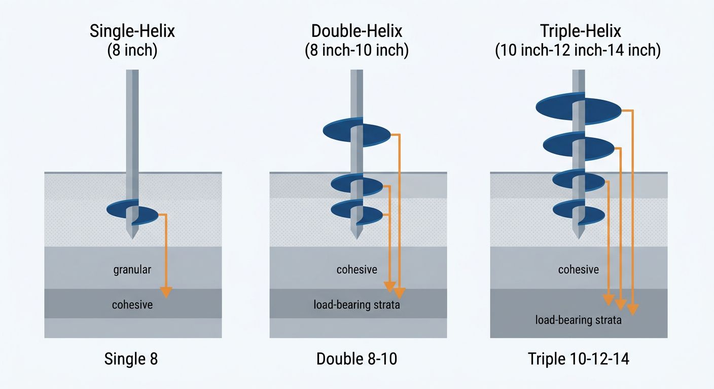
Three helical pile configurations: single, double, and triple helix with soil profiles
For cohesive soils, larger diameters are often recommended, while granular soils may require specific spacing. Helical pile for solar panel foundations typically demand wider diameters or multi-helix configurations to resist overturning.
We recommend consulting our engineering team to confirm that the selected configuration meets project loads and complies with ICC-ES AC358 acceptance criteria and applicable building codes. Consult a structural engineer or the manufacturer’s engineering team for project-specific design and installation guidance. Helical Technology supplies ICC- and ISO-certified products, ensuring reliable performance.
Calculate Shaft and Helix Bearing Capacities
With the helical pile components described in the previous section, the next step is to determine their uplift resistance capacity. Shaft capacity arises from frictional resistance between the soil and the pile shaft along its embedded length. Helix bearing capacity is the end bearing resistance of each helix plate, summed for multiple helices. Total compressive capacity equals shaft capacity plus the sum of individual helix bearing capacities; for tension loading, conservative designs often disregard shaft friction.
Field estimation often uses torque correlation: capacity = Kt × T (installation torque). Ultimate capacity must be verified through load testing or engineering analysis. The National Foundation Repair Association promotes industry best practices for capacity verification. These calculations are crucial for lateral load resistance in retaining walls and uplift resistance capacity in helical pile design for solar panel foundations. Our ICC-certified products and real-time design software support accurate capacity modeling. Capacities are validated through load testing and design verification, as will be discussed in the following section.
Combine Components for Ultimate Uplift Capacity
Combining leader sections, extension shafts, and multiple helix plates significantly increases the uplift resistance capacity of a helical pier. Our advanced earth anchoring systems are engineered for versatile foundation repair solutions.
By adding extension shafts, we can reach deeper load-bearing soil to improve pullout resistance. The combined components are installed following standard helical pier installation procedures, ensuring proper seating and torque verification. This directly influences uplift resistance capacity.
Multiple helix plates of increasing diameter on a single shaft distribute uplift forces more effectively than a single helix. For solar panel foundations, a helical pile for solar panel foundations with larger-diameter plates resists high uplift loads. Proper shaft diameter and helix spacing further enhance lateral load resistance.
We recommend consulting a structural engineer or our engineering team for project-specific design, as our ICC and ISO certified products comply with ICC-ES AC358.
Apply Safety Factors per ASCE 7
After determining the various load magnitudes, the next step is to apply ASCE 7-22 safety factors to establish the required uplift resistance capacity for helical piers. For uplift, the combination 0.6D + W typically governs, while lateral loading may use 1.0W or 1.2D + 1.6L + 0.5W. ASCE 7 mandates a minimum factor of safety of 1.5 for dead loads and 2.0 for live and wind loads when designing helical piers for uplift. However, in regions with expansive clay, such as those in Texas where moisture fluctuations can cause volume changes up to 4.5 percent, the soil’s movement can reduce effective pier capacity; our field experience with concrete pier foundation repair in Texas shows that these conditions warrant a higher factor—typically 2.5 instead of 2.0—to ensure adequate lateral load resistance and uplift stability. This same ASCE 7-compliant approach applies to helical pile for solar panel foundations, where lateral design loads also require careful factoring. The factored loads are then used in the capacity equation shown next.
Because soil conditions vary, always consult a local structural engineer or Helical Technology’s engineering team for project-specific ASCE 7 safety factor application.
Verify Capacity with On-Site Tests
To ensure that every helical pier installation performs as designed, we conduct on-site load tests that measure uplift resistance capacity and lateral load resistance. A pull-out test applies a controlled upward force to the pier, confirming that its vertical load capacity meets the engineered requirements for the soil and pier configuration. For applications such as helical pile for solar panel foundations, lateral load resistance testing is equally critical because these structures must withstand sustained horizontal wind and seismic forces. Our network of structural engineers provides detailed test protocols and documentation that align with ICC-ES acceptance criteria AC358, helping contractors verify full compliance. On-site load testing is not an optional step—it is the definitive method to verify that the installed helical piers provide the required capacity and durability for building foundation reinforcement, especially in variable soil conditions.
Prepare Design Documentation
After gathering site data, accurate design documentation begins with site-specific soil data to determine uplift resistance capacity, as emphasized by the International Society for Soil Mechanics and Geotechnical Engineering (ISSMGE). Our advanced earth anchoring systems rely on precise integration of the following elements:
- Integrate geotechnical report findings to calculate uplift resistance capacity for each pier location.
- Specify lateral load resistance requirements and confirm the selected helical pier configuration meets these demands.
- Record the helix plate size, number of helixes, and installation depth; for solar panel foundations, include the helical pile for solar panel foundations design parameters.
- Attach ICC-ES documentation, manufacturer certifications, and structural engineer load assumptions, including design software outputs such as HeliCAP®.
- Add a sign-off line for our network of structural engineers or the manufacturer’s engineering team per Helical Technology’s support process.
Consult a structural engineer or our engineering team for project-specific design and installation guidance. Complete documentation ensures code compliance; submit it to our engineering team for review to proceed with confidence and benefit from Engineering Excellence and Design Support.
Common Challenges in Uplift Capacity Estimation
While understanding uplift capacity is fundamental, accurately predicting the uplift resistance capacity of helical piers presents several common challenges. The complexity of soil behavior and the interplay of multiple piers require more than simple calculations. We recommend consulting a structural engineer or the manufacturer’s engineering team for project-specific design and installation guidance.
Key difficulties include:
- Soil variability: The uplift resistance of a helical pier depends heavily on soil type. Cohesive clays and granular sands exhibit different failure mechanisms, making torque-to-capacity correlations less reliable without site-specific geotechnical data.
- Torque correlation limits: Empirical formulas like the Meyerhof method provide useful starting points, but they often fail to capture local soil conditions. Overreliance on these correlations can lead to underestimating uplift requirements.
- Group effects: When multiple helical piers are installed in close proximity, the overlapping stress zones can reduce the net ability to resist pullout. Group interaction factors are not always well captured by standard design software.
- Solar panel foundations: For a helical pile for solar panel foundations, engineers must evaluate uplift resistance capacity and lateral load resistance simultaneously. Wind and seismic forces introduce complex multi-directional loads that challenge traditional uplift-only analyses.
Industry guidelines from the Foundation Repair Association and from the deep foundations trade association address these challenges, but they emphasize the need for site-specific load testing and engineering judgment.
These challenges underscore why careful engineering and load testing are essential—topics we will explore next.
Engineer Confident Foundations with Helical Technology
To achieve the engineering confidence these challenging conditions demand, our advanced earth anchoring systems provide foundations that handle uplift resistance capacity by transferring structural loads to competent soil strata. This torque-monitored installation process ensures long-term stability for residential and commercial projects.
Our engineering team delivers real-time design software and a network of structural engineers to compute lateral load resistance tailored to each site. We back every helical pier installation with ICC-ES (AC358) and ISO certified products—recognized by the National Foundation Repair Association as industry best practices. This integrated support guarantees that each foundation repair meets load-bearing and code requirements. The technology’s versatility extends to applications such as helical pile for solar panel foundations, where uplift performance is crucial.
With this engineering backbone, our installation process ensures lasting results. For project-specific design and installation guidance, consult a structural engineer or the manufacturer’s engineering team.
Resources
- Install Helical Piers for Existing Residential Foundations
- Reinforce Building Foundations with Helical or Push Piers
- Learn Concrete Pier Longevity in Texas Expansive Soils
- Find Crawl Space Repair and Waterproofing Services Near You
- Explore Helical Pier Installation Guide with Torque Monitoring
- Get Foundation Repair Cost Estimates for San Antonio Texas
- Discover Concrete Piers for Slab Foundation Repair in Texas
- Explore Geotechnical Engineering Resources from ISSMGE
- Join NFRA for Foundation Repair Certification and Resources
- Discover ADSC-IAFD Resources for Deep Foundations Industry