
Jason Keefer
President
Helical Pier System Termination
Table of Contents
Understanding Helical Pier System Termination
Building on helical pile installation basics, helical pier system termination marks the precise moment when the helical pile reaches target installation torque, depth refusal, or verified load capacity. We at Helical Technology emphasize this critical endpoint to ensure foundation repair solutions perform reliably. Proper termination prevents structural risks and optimizes load transfer.
Key helical pier termination criteria include:
- Achieving 90% of design torque, confirming soil capacity via torque correlation.
- Visual soil refusal, advancing less than 1 inch per rotation.
- Confirmatory quick load tests to verify performance.
Monitoring relies on torque indicators and drive-head readouts for real-time data. Operators cross-check torque logs with visual observations to avoid premature termination or excessive rotation that could compromise pile structural integrity. These readings are recorded and compared to project specifications to document conformance and inform any on-site adjustments. Helical pier brackets serve as termination fittings, connecting the pile shaft directly to the structure without further embedment. Common errors, like premature stopping or over-rotation causing damage, are avoided by adhering to these metrics. Safety protocols demand bracket alignment verification before connections.
Once termination is confirmed, proceed to structural connections. Consult our network of structural engineers for project-specific guidance to uphold ICC and ISO certified standards.
Fundamentals of Helical Pier Termination
Once helical piers reach the target depth during installation, proper termination ensures reliable load transfer to the supported structure. Helical pier system termination refers to the critical connection method between the pier shaft and the structure, utilizing specialized fittings to effectively transfer axial and lateral loads in a complete helical pier system. These fittings are essential for foundation repair and new construction, providing structural integrity while meeting rigorous code requirements.
We distribute a range of termination options at Helical Technology, each designed for specific applications. Headed bolts suit new construction connections, particularly residential foundations, offering capacities of 10-50 tons in galvanized steel. Bracket assemblies excel in underpinning existing structures for slab and wall repair, with helical pier brackets delivering 30-100 tons using ASTM A36 steel. Tieback terminations provide wall stabilization and lateral resistance at 5-25 tons with corrosion-resistant materials.
The following table compares key termination fittings available for helical piers, including applications and features relevant to foundation repair:
| Fitting Type | Primary Application | Material Options | Typical Load Capacity |
|---|---|---|---|
| Headed Bolt | New construction connections | Galvanized steel | 10-50 tons |
| Bracket Assemblies | Underpinning existing structures | ASTM A36 steel | 30-100 tons |
| Tieback Terminations | Wall stabilization | Corrosion-resistant | 5-25 tons |
Common Types of Helical Pier Termination Fittings, based on Helical Technology product catalog and ICC-ES evaluation reports.
This comparison highlights how bracket assemblies offer the highest load capacities for demanding repair scenarios, while headed bolts provide cost-effective solutions for new builds. Tiebacks prioritize lateral support in corrosion-prone environments. Selecting the right fitting depends on project demands, balancing capacity with site-specific conditions. These options ensure versatile termination of helical pier systems across residential and commercial applications.
Termination criteria include adequate embedment depth, grout encasement where required, and verification of load transfer. According to authoritative International Code Council standards in Section 1810.3.3.1.9, helical pile termination configurations must detail connections, grout requirements, and testing protocols. Helical pier termination criteria emphasize torque-to-capacity ratios and professional verification to confirm axial capacity.
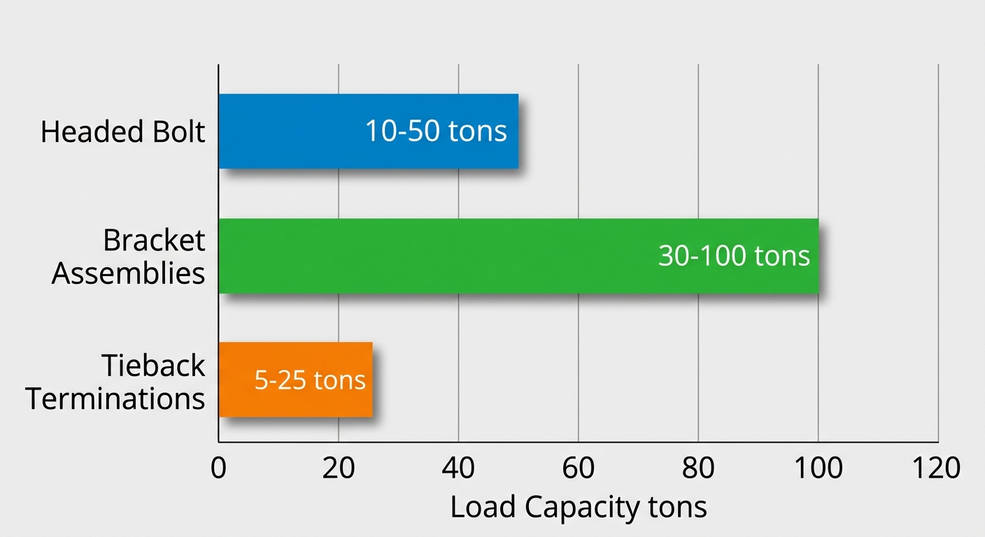
Typical load capacities of helical pier termination fittings comparison
Factors influencing termination selection encompass soil conditions, structure type, load demands, and corrosion protection needs. In variable soils, higher-capacity brackets prevent settlement, while coastal projects favor galvanized or coated options. Best practices include torque correlation to capacity during installation and oversight by our network of structural engineers. Products must comply with ICC-ES AC358; consult a structural engineer or our engineering team for project-specific guidance.
Understanding these fundamentals of helical pier termination processes prepares for advanced topics in load testing and case studies.
Mechanics of Helical Pier Termination
Once helical pier driving advances the foundation elements to the required position, proper helical pier system termination becomes critical to ensure load-bearing capacity and long-term stability. At Helical Technology, we emphasize precise termination mechanics to meet helical pier termination criteria, aligning with industry standards for reliable foundation repair solutions.
Torque and Depth Criteria
Standard torque and depth criteria form the foundation of successful helical pier system termination. Engineers typically target torque values such as 15-25 kip-ft for sandy conditions and 20-35 kip-ft for clay, as these indicate sufficient soil resistance and embedment. Depth determination relies on torque correlation, requiring the pier to extend at least 5 ft beyond the final helix to achieve full capacity, per authoritative building code standards from the International Code Council (ICC) in Sec 1810.3.3.1.9.
We recommend continuous monitoring during installation to confirm these helical pier termination criteria. Exceeding target torque signals achievement, while depth ensures the helix plates engage competent strata. This approach prevents under-installation, safeguarding structural integrity in projects across our service areas.
Our Helical Technology design software predicts optimal torque based on geotechnical data, enhancing accuracy for contractors. These criteria not only verify performance but also comply with ICC requirements for soils and foundations.
Soil Influence on Termination
Soil types significantly influence helical pier system termination decisions, demanding tailored adjustments to torque, depth, and verification. Sandy soils, with their granular nature, often allow shallower embedment around 15-25 ft, relying on torque correlation for confirmation due to consistent frictional resistance. In contrast, cohesive clay soils necessitate deeper penetration up to 20-40 ft and load tests to account for potential setup time and variable shear strength.
These variations highlight the need for site-specific evaluations. Helical pier termination criteria must adapt to soil stratigraphy, preventing refusal in loose layers or excessive embedment in dense zones. The International Code Council (ICC) standards guide these adjustments, ensuring compliance through verified methods.
The following table illustrates key differences in torque criteria by soil type:
| Soil Type | Torque (kip-ft) | Depth Range (ft) | Verification Method |
|---|---|---|---|
| Sandy | 15-25 | 15-25 | Torque correlation |
| Clay | 20-35 | 20-40 | Load test |
This comparison underscores how sandy conditions prioritize torque monitoring for efficiency, while clay requires confirmatory testing to validate capacity. At Helical Technology, our network of structural engineers uses these benchmarks alongside our real-time design software to optimize termination for diverse soil profiles, promoting ICC and ISO certified product performance.
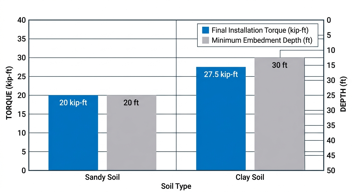
Torque and depth criteria by soil type for helical pier termination
Visualizing these criteria reinforces the practical adjustments needed. For instance, the chart highlights torque disparities, aiding contractors in preempting installation challenges and ensuring foundation repair solutions meet project demands.
Installation Achievement Methods
Achieving helical pier termination follows a structured process we outline for our certified installers. First, monitor installation torque continuously using calibrated drive heads, targeting values like 15-25 kip-ft in sand or 20-35 kip-ft in clay. Halt driving upon reaching preset torque or depth, confirming embedment exceeds 5 ft beyond the final helix per ICC Sec 1810.3.3.1.9.
Next, attach termination hardware such as helical pier terminations or helical pier brackets to transfer loads effectively. Perform pullout or compression load tests for verification, especially in clay, to simulate real conditions and document capacity.
- Advance piers while logging torque and depth data.
- Stop at target metrics and inspect helix engagement.
- Conduct proof tests per code standards.
- Secure with brackets and extensions for final assembly.
Our Helical Technology design software provides predictive modeling upfront, while post-termination verification confirms safe loading. Consult our structural engineering team for project-specific guidance to comply with applicable building codes and ICC-ES criteria.
Practical Termination Techniques
Building on helical pier design principles, practical helical pier system termination techniques ensure secure connections between helical piers and structures. At Helical Technology, we provide ICC-approved brackets and accessories that meet rigorous standards for foundation repair solutions. These methods, including bracket installation and selection, comply with authoritative building code standards from the International Code Council (ICC) in Sec 1810.3.3.1.9, emphasizing proper securement for helical pile terminations. Our advanced earth anchoring systems support contractors nationwide with engineering excellence and design support.
Bracket Installation Steps
Installing helical pier brackets requires precision to achieve optimal load transfer and alignment. Follow these step-by-step guidelines for secure helical pier system termination:
- Align the bracket with the pier shaft: Position the bracket flush against the exposed helical pier top after achieving target torque. Use a laser level to ensure the pier remains plumb within 1 degree tolerance.
- Secure with high-strength bolts: Insert manufacturer-specified bolts, such as 1-inch diameter Grade 8, through pre-drilled holes. Apply anti-seize compound to prevent corrosion.
- Verify plumbness using levels: Check vertical alignment with a 4-foot spirit level on multiple planes. Adjust if necessary before final torquing.
- Torque to manufacturer specs: Tighten bolts to 150 ft-lbs or as specified in installation manuals, using a calibrated torque wrench. Recheck after 24 hours for settlement.
These steps, aligned with ICC EPCOTBC 2024 standards, minimize risks in pier cap methods. We recommend our certified installers for complex projects to ensure compliance and performance.
Selecting and Preparing Brackets
Selecting the right helical pier brackets demands attention to helical pier termination criteria like load demands, soil corrosivity, and project scope. Key criteria include:
- Match load requirements: Choose brackets rated for at least 1.5 times the calculated structural load, such as 60-ton capacity for heavy commercial lifts.
- Account for soil conditions: In corrosive soils, opt for hot-dip galvanized or stainless steel options to extend service life beyond 50 years.
- Consider project type: Bolt-on brackets suit retrofits for minimal disruption, while welded types fit new construction for seamless integration.
Preparation involves cleaning the pier top of debris, abrading surfaces for better adhesion, and pre-assembling hardware. At Helical Technology in Littleton, CO, our ICC and ISO Certified products come with detailed guides. Always consult a structural engineer or our engineering team for project-specific design and installations must comply with applicable building codes and ICC-ES acceptance criteria (AC358). This approach ensures bracket finishing techniques deliver reliable ending helical piers.
Load Capacity and Suppliers
Common helical pier brackets offer impressive capacities suited to diverse applications. The Opportunity Bracket handles 60-90 tons, ideal for high-load underpinning, while the Plate Bracket supports 40-70 tons for standard repairs. We at Helical Technology supply these galvanized options, including tieback terminations for lateral restraint in wall stabilization projects. Our catalog features products from trusted US manufacturers, with on-site training to optimize usage.
Key US suppliers like Helical Technology provide hot-dip galvanized brackets resistant to harsh environments. These align with ICC Sec 1810.3.3.1.9 for secure terminations, ensuring foundation repair solutions perform under tension and compression.
The following Helical Pier Bracket Comparison table outlines key differences, drawn from Helical Technology catalog and installation manuals:
| Bracket Type | Installation Method | Load Capacity (tons) | Corrosion Resistance |
|---|---|---|---|
| Opportunity Bracket | Bolt-on | 60-90 | Galvanized |
| Plate Bracket | Welded | 40-70 | Hot-dip galvanized |
Opportunity Brackets excel in retrofits due to their bolt-on simplicity and higher capacity range, making them versatile for varying soil profiles. Plate Brackets, with welded permanence, suit permanent new builds but require skilled welding per code. Selecting based on these factors optimizes performance while controlling costs.
These techniques enable reliable helical pier projects, as demonstrated in upcoming case studies.
Advanced Termination Considerations
Beyond standard depths, advanced considerations for helical pier system termination ensure optimal load transfer and long-term stability in demanding soil conditions. At Helical Technology, we emphasize verification methods like torque and load tests to confirm proper installation, aligning with ICC and ISO Certified products for foundation repair solutions. These protocols address complex scenarios, such as variable subsurface profiles, where precise termination prevents settlement risks. Engineering manuals and our Helical Technology training outline practical steps for contractors to achieve reliable outcomes.
Verification methods play a crucial role in validating termination of helical pier systems. The comparison below outlines key testing approaches, their applications, accuracy, and code compliance.
Verification Methods for Termination
| Method | Application | Accuracy | Code Compliance |
|---|---|---|---|
| Torque Test | Real-time during install | High | ICC approved |
| Load Test | Post-install verification | Very high | Required for critical |
Torque tests provide real-time feedback during helical pier installation, offering high accuracy for standard compliance as ICC approved. Load tests, conducted post-installation, deliver very high accuracy and are essential for critical structures. Supporting data from engineering manuals reinforces these as industry best practices. Criteria for helical pier termination, including correlation between torque and capacity, guide selection of the appropriate method.
International Code Council (ICC) standards in EPCOTBC 2024 Part 1 Chapter 18 Sec 1810.3.3.1.9 cite authoritative building code requirements for helical pile termination in soils and foundations, specifying verification testing methods. Helical pier brackets facilitate achieving target depths and capacities by securely connecting piers to structures, enhancing load distribution. Load tests prove particularly vital in demanding applications, especially in Steel Foundation Underpinning projects requiring exceptional verification.
These methods ensure compliance and safety before full deployment, paving the way for successful installation case studies. Consult our network of structural engineers for project-specific guidance.
Common Questions on Helical Pier Termination
Following helical pier advancement, helical pier system termination confirms load capacity and installation success.
What is helical pier termination?
Helical pier system termination occurs when target torque or depth is reached, verifying the pier achieves designed load-bearing capacity through measured resistance.
What are helical pier termination criteria?
Helical pier termination criteria encompass torque correlation to capacity, settlement limits under test load, and installer verification we provide through engineering support.
How do helical pier brackets factor into termination?
Post-termination of helical pier systems, helical pier brackets connect piers to the structure, enabling efficient load transfer from foundation to stable soil.
What indicates successful termination?
Signs include consistent torque readings, no further advancement, and pullout resistance tests confirming embedment.
Does termination guarantee zero movement?
No, a common myth; it incorporates a factor of safety for minimal elastic movement. For deeper challenges, explore Deep Foundation Stabilization techniques.
Contact Helical Technology experts for site-specific guidance. Post-termination, explore maintenance best practices.
Achieving Reliable Termination Outcomes
Once shafts are advanced, focus shifts to precise helical pier system termination. We monitor the torque-to-turn ratio as primary helical pier termination criteria, targeting 5-10 inches per 360-degree rotation for most soils.
Post-installation, quick load tests verify capacity meets design loads with deflection under 0.1 inches. Attach helical pier brackets to foundations using corrosion-resistant hardware, maintaining alignment tolerances below 1/4 inch. Document termination depth, torque readings, and test results for quality assurance. Avoid over-rotation pitfalls through real-time installer training.
These methods ensure reliable outcomes ready for load testing.
This article was researched and written with the assistance of AI tools.