

Table of Contents
- Helical Pile Load Testing Fundamentals
- Standard Methods for Helical Pile Load Testing
- Why Load Testing Matters for Helical Pile Installations
- Conducting a Helical Pile Load Test: Step-by-Step
- Best Practices for Accurate Helical Pile Load Testing
- Helical Pile Load Testing: A Path to Foundation Reliability
Helical Pile Load Testing Fundamentals
Beyond installation basics, verifying performance through load testing is essential. Understanding helical pile load testing methods is critical for confirming that the installed piles will support the intended structural loads. We rely on two primary testing methodologies to validate design assumptions and ensure installation quality: the static load test and the torque correlation method.
Static Load Testing (ASTM D1143)
The ASTM D1143 static load test is the definitive procedure for verifying helical pile capacity. This method involves using a hydraulic jack and calibrated gauges to apply incremental loads to the pile while precisely measuring settlement. After each incremental load is applied, the pile movement is monitored and recorded, with each increment held until the rate of settlement substantially diminishes. The load-settlement data from this test allows our engineering team to verify that the pile’s behavior aligns with project specifications and ICC-ES acceptance criteria (AC358).
Torque Correlation Method
The torque correlation method provides a practical verification during installation. By monitoring the installation torque and applying a helical pile torque correlation factor (Kt), we can estimate the pile’s ultimate capacity in real-time. The relationship between installation torque and capacity is well-documented, though the specific Kt value can vary based on soil conditions and helix pitch. We use this method to confirm that the pile is achieving the required capacity before moving to the next location.
Load testing is frequently required by building codes for high-load or critical applications. Test results often drive final decisions on pile length and helix configuration, which is why all load test data should be reviewed by a qualified professional. For accurate interpretation and project-specific design, professional structural engineering for helical piles is recommended. With load test results in hand, engineers can finalize design parameters.
Consult a structural engineer or the manufacturer’s engineering team for project-specific design and installation guidance.
Standard Methods for Helical Pile Load Testing
To ensure our foundation designs meet performance expectations, we rely on specific helical pile load testing methods that provide direct field verification of capacity. Both static and dynamic protocols allow us to confirm that installed helical piers match or exceed the design loads. What follows breaks down the most widely used procedures for testing helical piles.
Static Load Testing Procedures
The primary protocol for static testing is the ASTM D1143 pile load test, which outlines a detailed, step-by-step approach for measuring axial capacity. We set up a reaction frame – typically using adjacent anchor piles or weighted deadmen – and align a hydraulic jack directly over the test pier. A calibrated load cell sits between the jack and the pile head, while a reference beam supports dial gauges or electronic displacement transducers that track head movement independently of ground disturbance.
During the test, we apply compressive load in increments – usually 10 to 25 percent of the anticipated ultimate capacity – and hold each step long enough for the rate of settlement to stabilize. Standard hold periods range from five to fifteen minutes per increment, depending on soil conditions and project requirements. We record both time and settlement at each interval, building a time-settlement curve that reveals creep behavior in cohesive soils.
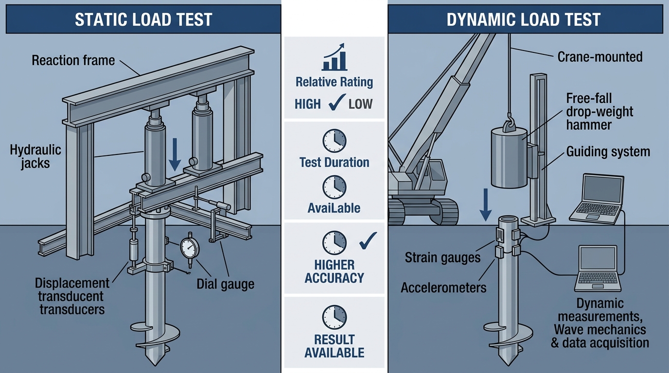
Professional comparison of helical pile load testing methods
Once maximum test load is reached – typically 200 percent of the design working load – we unload in decrements, observing rebound. The completed data set yields a load-settlement curve that we interpret to confirm the pile has adequate geotechnical and structural capacity under code-mandated safety factors.
Dynamic Load Testing Approaches
Dynamic testing uses a rapid force pulse – either from a controlled Statnamic launch or a drop-weight impact – to mobilize pile resistance. A Statnamic test burns a propellant inside a sealed cylinder to accelerate a reaction mass upward, pushing the pile downward for about ⅔ of a second. This technique works well on congested sites where a heavy reaction frame cannot be placed. Drop-weight methods, by contrast, drop a steel hammer onto a cushion atop the pile, and we infer capacity from strain and acceleration records processed through wave equation analysis.
Dynamic testing is typically faster and less expensive to mobilize than a full static setup, but it rarely stands alone for helical piles. Helical bearing plates interrupt the wave front in a way that complicates signal interpretation, so dynamic predictions nearly always need correlation with at least one static test on the same project. For routine quality assurance we often check the helical pile torque correlation factor – an empirical relationship between installation torque and ultimate capacity – to flag under-performing piles between formal tests. This correlation is a useful field indicator, but it does not replace the load test.
The following table summarizes how the two primary load testing methods compare across the key factors that influence a contractor’s choice.
| Aspect | Static Load Test | Dynamic Load Test |
|---|---|---|
| Cost | High – requires reaction frame and heavy equipment | Moderate – less equipment but specialized analysis |
| Duration | Several hours to days | Minutes to a few hours |
| Accuracy | High – direct measurement of load vs. settlement | Moderate – requires correlation with static tests |
| Application | Standard for design validation and code compliance | Quality assurance, rapid field verification |
Choosing between static and dynamic testing depends on project scale, access, and the level of certainty required. For design validation and code compliance, a static test following the ASTM D1143 standard remains the benchmark. Dynamic testing serves a valuable role in rapid QA screening, provided the results are correlated with static test data from the same site. Our Engineering Excellence and Design Support team can help contractors develop a testing program that matches project conditions while ensuring ICC and ISO Certified products perform as intended.
Consult a structural engineer or the manufacturer’s engineering team for project-specific design and installation guidance. Product certifications must comply with ICC-ES acceptance criteria.
Why Load Testing Matters for Helical Pile Installations
Understanding helical pile load testing methods begins with recognizing why testing is a non-negotiable quality assurance step for every project. Helical piles are a proven solution for foundation repair, including pier and beam repair in Austin, but their performance depends entirely on proper load testing to confirm they meet design and safety requirements.
Verifying Design Capacity
Load testing is the only way to verify that an installed pile meets the geotechnical and structural assumptions made during design. Through a controlled ASTM D1143 static load test, we measure actual pile settlement under incremental loads, confirming that the foundation system can safely support the structure. Without this field validation, engineers must rely on theoretical models that can’t account for real-world variability.
One critical aspect we evaluate is the helical pile torque correlation factor. During installation, torque readings give us an immediate estimate of capacity, but this correlation between torque and ultimate load must be validated on-site. Field testing confirms whether the estimated factor accurately predicts performance in the actual soil conditions encountered.
Load tests also reveal hidden site conditions that pre-installation geotechnical reports might miss:
- Soil variability: Strata can change significantly over short distances, altering bearing capacity from what the borings indicated.
- Damaged helices: Test loads can expose plates that were deformed during installation through debris or obstructions.
- Inadequate embedment: If a pile terminates too shallow in the bearing stratum, the load test will show excessive settlement.
- Subsurface obstructions: An obstruction deflecting a pile can create eccentric loading that a load test will detect before it becomes a structural problem.
Each of these verification steps ensures that the delivered capacity matches the engineering design, protecting the structure’s long-term integrity.
Ensuring Code Compliance
For commercial applications, load testing is more than a best practice—it’s a code requirement. The International Building Code (IBC) and many local codes mandate field verification of pile capacity. Our products align with ICC-ES AC358 acceptance criteria for helical pile systems, and our ICC/ISO certification provides a significant compliance advantage by demonstrating that the manufactured components meet rigorous standards.
However, it’s crucial to understand that product certification does not replace project-specific load testing. As our ICC/ISO certification FAQ confirms, certified products support code compliance, but the installed system must still be field-tested to prove it performs as designed in the project’s unique soil profile.
Key compliance considerations include:
- Building code mandates: Most commercial helical pile projects require at least one static load test per unique soil condition on site.
- ICC-ES AC358 alignment: This acceptance criteria sets the methodology and performance benchmarks that our certified products are designed to meet.
- Manufacturer support: Our network of structural engineers provides project-specific guidance to design a load testing program that satisfies the reviewing building official.
Products are certified to ICC/ISO where indicated — installations must comply with applicable building codes and ICC-ES acceptance criteria (AC358).
By integrating load testing into every critical project, we ensure that the installed foundation system not only meets but exceeds the required safety and performance standards. With this importance established, let’s explore the specific methods used to test helical pile capacity — from torque correlations to static load tests.
Consult a structural engineer or the manufacturer’s engineering team for project-specific design and installation guidance.
Conducting a Helical Pile Load Test: Step-by-Step
Pre-Test Preparations
Thorough preparation is essential for obtaining accurate and repeatable results. Begin by selecting a test location that is level, accessible, and representative of the site’s soil conditions; it should be at least 5ft from any structures to avoid influence from existing foundations. Install at least two reaction piles using the same method and equipment as the production piles. These reaction piles must have a combined capacity of at least 1.5× the expected maximum test load to provide a stable reaction frame. The installation of all piles should follow our manufacturer guidelines for helical pier installation, as proper alignment and torque monitoring are critical to downstream data reliability.
We can also use the helical pile torque correlation factor during setup to estimate the ultimate capacity. This real-time correlation helps confirm that the installed pile is likely to achieve the target test load and is consistent with site expectations.
Next, assemble the loading apparatus. Position a hydraulic jack equipped with a calibrated load cell over the test pile, and connect it to a manual or electronic pump. Confirm that the load cell’s calibration certificate is dated within the last 12 months. Attach at least two dial gauges—each with a resolution of 0.001in—to an independent reference beam that will not move during the test; zero all gauges before loading begins. For safety, maintain a clear zone around the jack, require hard hats and steel-toe boots, and establish an emergency stop procedure. During equipment setup, use a crimper to secure reaction cable connections, ensuring all hydraulic hoses and linkages are properly fastened.
Executing the Test and Recording Data
The static load test should proceed according to the ASTM D1143 static load test standard. Apply the load in equal increments, typically 25% of the design load, and hold each increment for a minimum of 5 minutes or until the settlement rate stabilizes—defined as 0.01in of movement in a 2-minute period. At the end of each increment, record the time, applied load, and cumulative settlement from all dial gauges.
Continue this loading sequence until you reach one of two defined endpoints: plunging failure (rapid, continuous settlement under a constant load) or a maximum test load of 200% of the design load. After reaching the peak load, unload in 50% decrements with corresponding hold times to capture the pile’s rebound behavior. This unloading data is valuable for evaluating the elastic versus plastic settlement of the system.
Following the test, plot a load-settlement curve to interpret the results. Identify the ultimate capacity as the load at which settlement equals 0.05 inches per diameter of the pile, or the point of tangency on the curve, as defined by the interpretation method you adopt. Finally, compare the measured ultimate capacity to the value predicted by the torque correlation factor from the manufacturer. A close alignment between these data sets validates the installation process and confirms the reliability of our advanced earth anchoring systems.
Consult a structural engineer or the manufacturer’s engineering team for project-specific design and installation guidance. Products are certified to ICC/ISO where indicated—installations must comply with applicable building codes and ICC-ES acceptance criteria (AC358).
Best Practices for Accurate Helical Pile Load Testing
Torque-to-Capacity Correlation
We use the torque-to-capacity correlation method to estimate the ultimate capacity of a helical pile during installation. The central relationship is Qu = Kt × T, where Qu is the ultimate pile capacity, T is the final installation torque, and Kt is the empirical helical pile torque correlation factor. This factor is not a universal constant; it varies with site conditions and must be calibrated for each project. According to manufacturer-provided technical guidance from Helical Technology, the Kt value is influenced by several key variables:
- Soil type: Cohesionless sands and cohesive clays produce different torque responses for the same capacity.
- Helix configuration: The diameter, number, and spacing of helical bearing plates directly affect the torque reading.
- Installation rate: Advancing the pile too quickly can artificially inflate torque values.
- Lead section geometry: The shaft diameter and shape alter the friction between the soil and the pile.
Because of these variables, torque-to-capacity estimates must always be validated. We require that the relationship be confirmed through a static load test conducted in accordance with the ASTM D1143 static load test standard. This validation step provides direct measurement of pile movement under load and confirms that the assumed Kt is appropriate for the specific conditions.
Common Pitfalls to Avoid
Even with a solid understanding of torque correlation, several testing errors can lead to inaccurate capacity assessments or even pile failure. Our in-house troubleshooting expertise, drawn from Helical Technology’s load test guidance, highlights these frequent issues and their solutions:
- Improper reaction pile spacing: Positioning reaction piles too close to the test pile creates soil interaction that distorts readings. We recommend a minimum center-to-center distance of five times the pile shaft diameter or eight feet, whichever is greater.
- Insufficient hold time: Failing to hold the load for the required duration masks creep behavior. For proof tests, we advise a minimum hold time of one hour, while extended creep tests often require a 12- to 24-hour hold period.
- Neglecting soil relaxation: In cohesive soils, pore water pressure generated during installation can temporarily increase capacity. A false reading occurs if the load is not read after a set hold period, allowing these pressures to dissipate.
- Ignoring temperature effects on equipment: Hydraulic load cells and jacks are sensitive to temperature swings. Daily equipment calibration checks are necessary because thermal expansion or contraction can cause false pressure readings and lead to incorrect load interpretation.
In advanced earth anchoring systems, attention to these details separates a successful verification program from a compromised foundation. We advocate for a methodical approach that pairs empirical torque monitoring with rigorously controlled static testing. Consult a structural engineer or the manufacturer’s engineering team for project-specific load test design and interpretation.
Helical Pile Load Testing: A Path to Foundation Reliability
Once the pile design is determined, load testing validates its capacity and ensures the foundation will perform as intended. The two primary helical pile load testing methods are the static load test and the torque correlation method, each playing a distinct role in capacity verification.
The static load test, performed in accordance with the ASTM D1143 static load test standard, is the definitive method for directly measuring a helical pile’s capacity. During this procedure, incremental loads are applied to the pile while precise settlement readings are recorded. Load is increased in steps and held at each stage, allowing engineers to observe the pile’s behavior under sustained force and confirm it meets project requirements without excessive displacement. This direct measurement is the benchmark against which other capacity verification methods are calibrated.
As an indirect method, the helical pile torque correlation factor uses installation torque to estimate the pile’s ultimate capacity. The relationship follows the formula Pu = kT, where Pu is the ultimate capacity, T is the final installation torque, and k is the torque correlation factor. This factor varies by soil type and must be calibrated against static load tests to be reliable. The torque-to-capacity relationship allows for real-time quality control during installation, with the understanding that project-specific conditions dictate the appropriate correlation value.
Load testing protocols are an essential quality-control step for both residential and commercial helical pile projects, verifying the design assumptions made by helical pile manufacturers and structural engineers. We provide engineering support to help installers interpret test results and apply correlations correctly, reducing foundation risk. When properly tested, helical piles deliver the reliable performance that structural integrity demands, confirming helical pile load testing methods as a critical component of foundation assurance.
Resources
- Find Qualified Structural Engineers for Helical Piles
- Get Professional Pier and Beam Repair in Austin
- Avoid Common Crimping Mistakes in Foundation Repair
- Get Door-to-Door Sales Marketing for Foundation Repair
- Get Certified Helical Pier Installation Training
- Identify Seawall Failure and Helical Pier Repair
- Compare Helical Piers vs Push Piers for Repair
- Find ASTM D1143 Standard for Pile Load Test